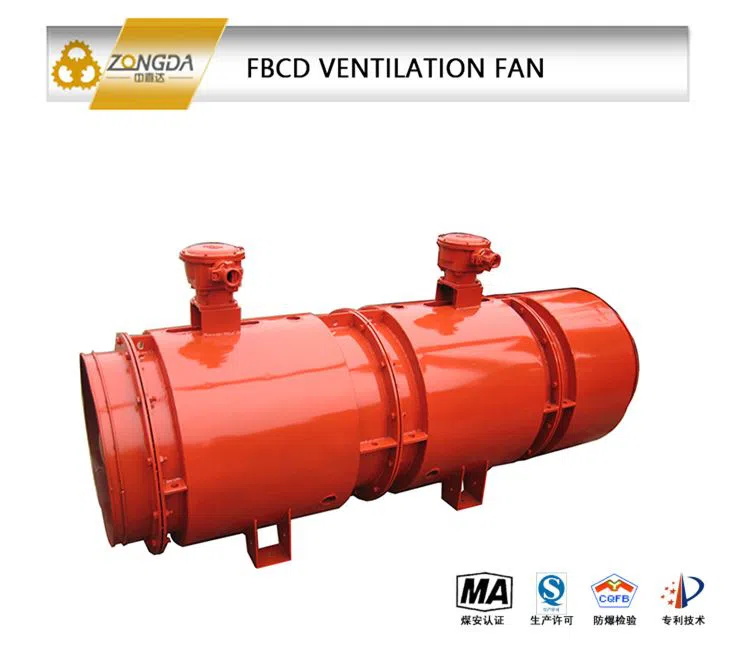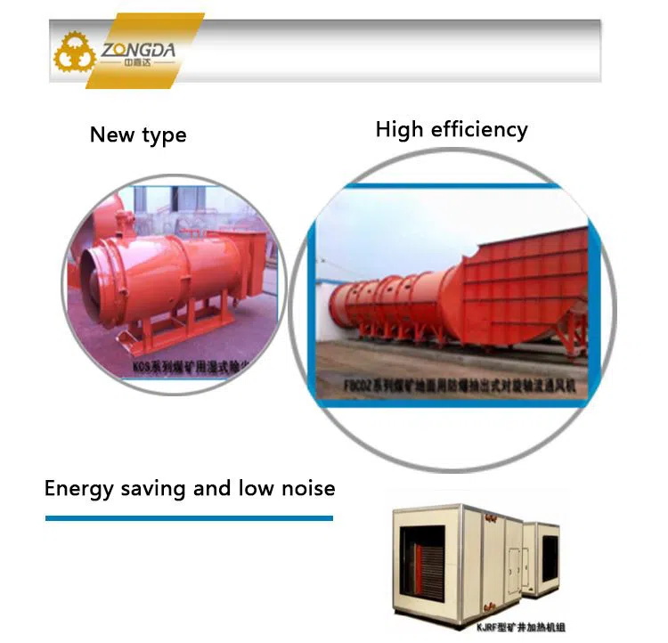


FBD series explosion proof ventilation fan (hereinafter referred to as fan) has the characteristics of reasonable structure, complete specifications, high efficiency, obvious energy saving effect, low noise, long air supply distance, etc.


FBD series explosion proof ventilation fan (hereinafter referred to as fan) has the characteristics of reasonable structure, complete specifications, high efficiency, obvious energy saving effect, low noise, long air supply distance, etc.
Product Specification
FBD series explosion proof ventilation fan (hereinafter referred to as fan) has the characteristics of reasonable structure, complete specifications, high efficiency, obvious energy saving effect, low noise, long air supply distance, etc.
According to different requirements of ventilation resistance, the whole machine can be used or used in different levels, so as to reduce the ventilation time and save energy. The length of the tunnel is less than 2000m, so it can not move the ventilator to supply air normally, which reduces the labor intensity of the workers and saves the ventilation time. It is an ideal equipment for local ventilation in the coal mine. At the same time, it can also be used in metallurgy, nonferrous metals, gold, chemical industry, shipbuilding, ceramics and other high-pressure ventilation occasions.
The structure of the ventilator is characterized by explosion proof ventilation fan, contra rotating, silencing and axial flow. It is mainly used in the coal mine with the risk of methane gas explosion, and can be used for the medium and long-distance ventilation of the coal mining face. At the same time, it is also suitable for local ventilation and tunnel ventilation in other mines.
Main purpose and scope of application
The normal working conditions of the fan are:
1) It is mainly used in the coal mine with the risk of methane gas explosion. It is installed in the air inlet tunnel and used together with the positive pressure air duct for the forced ventilation;
2) Medium temperature – 20 ℃ ~ + 40 ℃;
3) The altitude is less than 1000m;
4) The humidity is not more than 95% (at 25 ℃).
Standards For Fans
The fan shall comply with MT222<< Technical Conditions Of partial Fan for coal mine>> and Q /ZFJ002<< FBD series mining explosion proof ventilation fan press in counter rotating axial flow partial fan>>
Working principle of ventilator
Each stage of the fan is driven by a explosion proof ventilation fan motor with the same rated power. The impeller is directly installed on the shaft extension of the motor, and the rotation direction of the impeller between adjacent stages is opposite. After entering the first stage impeller to obtain energy, the gas is accelerated by the second stage impeller and then discharged by the third stage impeller or the fourth stage impeller. The rear stage impeller has the function of the stationary blade in the ordinary axial-flow fan. It can not only obtain the velocity component in the straight circumferential direction, but also increase the air flow energy, so as to achieve higher air pressure and efficiency than the ordinary axial-flow fan.
The mining explosion proof ventilation fan press in counter rotating axial flow local fan produced by our company adopts the newly developed patent technology <<Impeller Combination of Counter Rotating Axial Flow Fan>>, and also adopts the first domestic patent technology <<Automatic Switching Device>>
The patented product <<Automatic Switching Device>> is installed at the air outlet of the fan, to automatically realize the locking of the main and auxiliary fans. When the main fan is running, under the action of wind pressure, the automatic switching device of the main fan will automatically open and the automatic switching device of the auxiliary fan will automatically close.
Main performance characteristics
1. The fan is composed of two or more working motors, and the adjacent impellers rotate in relative direction. That is to say, the number of two stage blades is prime to each other. The energy of the air is obtained by the first stage impeller and is sent out after being pressurized by the second stage impeller. In addition to increasing the air flow energy, the second stage impeller also has the function of static guide vane in the ordinary axial flow fan. While obtaining the velocity component in the direction of straightening the circumference, the second stage impeller straightens the air flow impact, increases the air flow energy, reduces the wake vortex, and reduces the noise.
2. In the whole working condition of the fan performance curve, the performance of the fan is improved, the power of the two-stage impeller shaft is balanced, and the maximum power is equal. The key point is to solve the problem that the shaft power of the two-stage impeller in the original pair of cyclones is unbalanced. When the pipeline resistance increases, the increase of the second stage shaft power speed leads to the excessive shaft power of the impeller at the same level, which is easy to burn down the motor.
3. Under various working conditions, the wind pressure is relatively gentle, the surge phenomenon is small, the operation is also stable in the area of high wind pressure and small flow, the air supply distance is far in the underground, and the adaptability is strong to the complex roadway. Key solutions: low efficiency, high energy consumption and high noise of the original pair of cyclones.
4. The new type of explosion proof ventilation fan (automatic switching explosion-proof counter rotating axial flow partial fan) highlights the advantages of high air pressure, long air supply distance and convenient switching. Key solutions: requirements of “four complete”, “three special”, “two locking” and “one switching” in partial fan management.
Technical performance Parameters of Two Stages Ventilation Fan
| Type | Rotaltion Rate | Power | Rated Voltage
(V) |
Single Motor | Capacity M3/Min | Total Pressure Pa | Maximum Total Pressure
(%) |
A Sound Level (Db) | Outer Dimention |
| R/Min | Kw | Rated Current
(A) |
Φ×L(Mm) | ||||||
| №3.5 | 2840 | 2×2.2 | 380/660 | 4.8/2.8 | 204~126 | 760~1140 | 86 | 22 | 445×1135 |
| №4.0 | 2830 | 2×1.1 | 380/660 | 2.5/1.4 | 92~47 | 152~1707 | 86 | 22 | 575×1500 |
| 2×1.1(A) | |||||||||
| 2840 | 2×1.5 | 380/660 | 3.4/2.0 | 111~56 | 172~1933 | 86 | 22 | ||
| 2840 | 2×2.2 | 380/660 | 4.8/2.8 | 136~72 | 251~2156 | 86 | 22 | ||
| 2880 | 2×3 | 380/660 | 6.4/3.7 | 115~86 | 351~2300 | 86 | 22 | ||
| №5.0 | 2830 | 2×1.1(A) | 380/660 | 2.5/1.4 | 92~47 | 152~1707 | 86 | 22 | 700×1930 |
| 2900 | 2×4 | 380/660 | 8.1/4.7 | 184~102 | 231~2200 | 86 | 22 | ||
| 2900 | 2×5.5 | 380/660/1140 | 11.1/6.4/3.7 | 200~100 | 220~2950 | 86 | 22 | ||
| 2900 | 2×7.5 | 380/660/1140 | 14.8/8.7/5.0 | 255~155 | 380~3524 | 86 | 22 | ||
| №5.6 | 2900 | 2×7.5 | 380/660/1140 | 14.8/8.7/5.0 | 274~124 | 354~3573 | 86 | 22 | 770×2100 |
| 2930 | 2×11 | 380/660/1140 | 21.6/12.6/7.2 | 345~191 | 495~4518 | 86 | 22 | ||
| 2930 | 2×15 | 380/660/1140 | 28.8/17.0/9.6 | 395~250 | 700~4740 | 86 | 22 | ||
| №6.0 | 2930 | 2×15 | 380/660/1140 | 28.8/17.0/9.6 | 420~240 | 350~5150 | 86 | 22 | 820×2500 |
| 2930 | 2×18.5 | 380/660/1140 | 35.5/20.5/11.8 | 486~256 | 513~5330 | 86 | 22 | ||
| 2940 | 2×22 | 380/660/1140 | 41.0/24.4/13.67 | 525~310 | 615~5460 | 86 | 22 | ||
| №6.3 | 2930 | 2×15 | 380/660/1140 | 28.8/17.0/9.6 | 420~240 | 350~5150 | 86 | 22 | 850×2500 |
| 2930 | 2×18.5 | 380/660/1140 | 35.5/20.5/11.8 | 486~256 | 513~5330 | 86 | 22 | ||
| 2940 | 2×22 | 380/660/1140 | 41.0/24.4/13.67 | 525~310 | 615~5460 | 86 | 22 | ||
| 2950 | 2×30 | 380/660/1140 | 56.9/32.9/18.5 | 590~320 | 760~5900 | 86 | 22 | 850×2700 | |
| №7.1 | 2950 | 2×30 | 380/660/1140 | 56.9/32.9/18.5 | 620~370 | 600~6624 | 86 | 22 | 930×2740 |
| 2950 | 2×37 | 380/660/1140 | 67.9/40.3/22.6 | 745~400 | 890~6630 | 86 | 22 | ||
| 2970 | 2×45 | 380/660/1140 | 82.1/48.4/27.4 | 830~545 | 1450~6780 | 86 | 22 | 930×2830 | |
| №8.0 | 2950 | 2×30 | 380/660/1140 | 56.9/32.9/18.5 | 520~265 | 400~6600 | 86 | 22 | 1040×2760 |
| 2970 | 2×45 | 380/660/1140 | 82.1/48.4/27.4 | 680~380 | 600~7600 | 86 | 22 | 1040×2900 | |
| 2970 | 2×55 | 380/660/1140 | 102.6/59.3/34.3 | 820~480 | 700~8300 | 86 | 22 | 1040×3050 | |
| 2970 | 2×75 | 380/660/1140 | 140.1/80.7/46.7 | 1260~675 | 2160~7170 | 86 | 22 | 1040×3190 |
Technical performance Parameters of Three Stages Ventilation Fan
| Type | Rotaltion Rate | Power | Rated Voltage
(V) |
Single Motor | Capacity M3/Min | Total Pressure Pa | Maximum Total Pressure
(%) |
A Sound Level
(Db) |
Outer Dimention |
| R/Min | Kw | Rated Current
(A) |
Φ×L(Mm) | ||||||
| №4.0 | 2840 | 3×2.2 | 380/660 | 4.8/2.8 | 226~110 | 410~2590 | 86 | 22 | 575×2250 |
| 2880 | 3×3 | 380/660 | 6.4/3.7 | 226~120 | 410~2670 | 86 | 22 | ||
| 2890 | 3×4 | 380/660 | 8.1/4.7 | 226~146 | 410~3290 | 86 | 22 | ||
| №5.0 | 2900 | 3×5.5 | 380/660/1140 | 11.1/6.4/3.7 | 245~155 | 430~4430 | 86 | 22 | 700×2600 |
| 2900 | 3×7.5 | 380/660/1140 | 14.8/8.7/5.0 | 306~175 | 470~5000 | 86 | 22 | ||
| №5.6 | 2930 | 3×11 | 380/660/1140 | 21.6/12.6/7.2 | 408~194 | 500~6080 | 86 | 22 | 770×3560 |
| 2930 | 3×15 | 380/660/1140 | 28.8/17.0/9.6 | 460~245 | 600~7240 | 86 | 22 | ||
| №6.3 | 2930 | 3×18.5 | 380/660/1140 | 35.5/20.5/11.8 | 510~245 | 610~7850 | 86 | 22 | 850×3740 |
| 2940 | 3×22 | 380/660/1140 | 41.0/24.4/13.67 | 560~245 | 610~8560 | 86 | 22 | ||
| 2950 | 3×30 | 380/660/1140 | 56.9/32.9/18.5 | 640~252 | 620~9000 | 86 | 22 | ||
| №7.1 | 2950 | 3×37 | 380/660/1140 | 67.9/40.3/22.6 | 745~400 | 1170~9180 | 86 | 22 | 930×3830 |
| 2970 | 3×45 | 380/660/1140 | 82.1/48.4/27.4 | 830~545 | 1450~9220 | 86 | 22 | ||
| №8.0 | 2970 | 3×55 | 380/660/1140 | 102.6/59.3/34.3 | 990~625 | 1810~9330 | 86 | 22 | 1040×4250 |
Technical performance Parameters of Four Stages Ventilation Fan
| Type | Rotaltion Rate | Power | Rated Voltage
(V) |
Single Motor | Capacity M3/Min | Total Pressure Pa | Maximum Total Pressure
(%) |
A Sound Level (Db) | Outer Dimention |
| R/Min | Kw | Rated Current
(A) |
Φ×L(Mm) | ||||||
| №4.0 | 2840 | 4×2.2 | 380/660 | 4.8/2.8 | 226~110 | 525~3330 | 86 | 22 | 575×2820 |
| 2880 | 4×3 | 380/660 | 6.4/3.7 | 226~120 | 525~3980 | 86 | 22 | ||
| №5.0 | 2890 | 4×4 | 380/660 | 8.1/4.7 | 226~146 | 525~4220 | 86 | 22 | |
| 2900 | 4×5.5 | 380/660/1140 | 11.1/6.4/3.7 | 245~155 | 560~5690 | 86 | 22 | 700×3130 | |
| 2900 | 4×7.5 | 380/660/1140 | 14.8/8.7/5.0 | 306~175 | 590~6430 | 86 | 22 | ||
| №5.6 | 2930 | 4×11 | 380/660/1140 | 21.6/12.6/7.2 | 408~194 | 610~7350 | 86 | 22 | 770×4180 |
| 2930 | 4×15 | 380/660/1140 | 28.8/17.0/9.6 | 460~245 | 767~9380 | 86 | 22 | ||
| №6.3 | 2930 | 4×18.5 | 380/660/1140 | 35.5/20.5/11.8 | 510~245 | 785~10100 | 86 | 22 | 850×4460 |
| 2940 | 4×22 | 380/660/1140 | 41.0/24.4/13.67 | 560~245 | 785~11000 | 86 | 22 | ||
| 2950 | 4×30 | 380/660/1140 | 56.9/32.9/18.5 | 640~252 | 805~11570 | 86 | 22 | ||
| №7.1 | 2950 | 4×37 | 380/660/1140 | 67.9/40.3/22.6 | 745~400 | 1450~11830 | 86 | 22 | 930×4570 |
| 2970 | 4×45 | 380/660/1140 | 82.1/48.4/27.4 | 830~545 | 1810~11860 | 86 | 22 | ||
| №8.0 | 2970 | 4×55 | 380/660/1140 | 102.6/59.3/34.3 | 990~625 | 2160~11980 | 86 | 22 | 1040×5070 |
Depending on strong technical capability and rich experience, ZONGDA provides the EPC service to the domestic and international clients and has abundant EPC project experience in China.

Copyright © Qingdao Zongda Machinery Co., Ltd. All Rights Reserved.